The effect of change in V BE is negligible if V CC > V BE (V CC atleast 10 times greater than V BE). This will shift the Q-point (I C = βI B and V CE = V CC – I C R C). It is clear that decrease in V BE increases I B .

The expression for I B in base bias method is given by The base-emitter-voltage V BE decreases with the increase in temperature (and vice-versa).

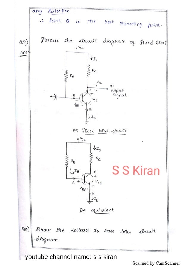
In addition to being affected by change in β, the Q-point is also affected by changes in V BE and I CBO in the base bias method. In base bias method, how Q-point is affected by changes in V BE and I CBO. Neglect any change in V BE and the effects of any leakage current. If β = 100 at 25☌ and 150 at 75☌, determine the percentage change in Q-point values ( V CE and I C) over this temperature range. 6 is subjected to an increase in temperature from 25☌ 5 shows CE amplifier using base resistor method of biasing. Calculate also the value of load resistance that would be employed. supply and a silicon transistor with β = 100. Design base resistor bias circuit for a CE amplifier such that operating point is V CE = 8V and I C = 2 mA. 4.Īpplying Kirchhoff ‘s voltage law to the base side and taking resistances in kΩ and currents in mA, we have, Calculate the values of three currents in the circuit shown in Fig. (ii) If another transistor of the same batch with β = 50 is used, what will be the new value of zero signal I C for the same R B ? Solution :Īs it is a Ge transistor, therefore, V BE = 0.3 V If theĬollector supply V CC = 12V, what is the value of R B in the base resistor method ? Take β = 100. (i) A germanium transistor is to be operated at zero signal I C = 1mA. Its co-ordinates are I C = 1mA and V CE = 4V. 3 (ii) shows the operating point Q on the d.c. 3(ii).Īs it is a silicon transistor, therefore, V BE = 0.7V. load line AB is constructed as shown in Fig. This locates the second point A (OA = 3mA) of the load line on the collector current axis. When V CE = 0, I C = V CC/R C = 6V/2 kΩ = 3 mA. This locates the first point B (OB = 6V) of the load line on collector-emitter voltage axis as shown in Fig. What is the stability factor ? Solution : load line and determine the operating point. 3 (i) shows that a silicon transistor with β = 100 is biased by base resistor method. (ii) When R B is made equal to 50 kΩ, then it is easy to see that base current is doubled i.e.


(i) Referring to Fig.2 (ii) and applying Kirchhoff ’s voltage law to the circuit ABEN, we get, It may be noted that negative terminals of the power supplies are grounded to get a complete path of current. Here, we need show only the supply voltages, + 2V and +9V. The same circuit is shown in a simplified way in Fig. 2 (i), biasing is provided by a battery V BB (= 2V) in the base circuit which is separate from the battery V CC (= 9V) used in the output circuit. (ii) If R B in this circuit is changed to 50 kΩ, find the new operating point. (i) Determine the collector current I C and collector-emitter voltage V CE . 2 (i) shows biasing with base resistor method. ∴ Base voltage (signal voltage) = Collector current / (5 mA/V )= 3 mA /( 5 mA/V) = 600 mV Q3. Fig. Now Collector current / Base voltage (signal voltage) = 5 mA/V allowed collector current, i C =12 V /R C = 12 V/ 4 KΩ = 3 mA allowed voltage across R C = 13 − 1 = 12 V What is the maximum input signal if β = 100 ? Given V knee = 1V and a change of 1V in V BE causes a change of 5mA in collector current. During the positive peak of the signal, i C = 1 + 1 = 2mAĪnd during the negative peak (point B), i C = 1 − 1 = 0 mA Q2. A transistor employs a 4 kΩ load and V CC = 13V.


 0 kommentar(er)
